topical media & game development


developments in hardware and software
Following Moore's law (predicting the doubling of computing power
every eighteen months),
computer hardware has significantly improved.
But perhaps more spectacular is the growth
in computing power of dedicated multimedia hardware,
in particular what is nowadays called the GPU
(graphics processing unit).
In
[Cg], he NVIDIA GeForce FX GPU
is said to have 125 million of transistors, whereas the Intel 2.4GHz
Pentium 4 contains only 55 million of transistors.
Now, given the fact that the CPU (central processing unit)
is a general purpose, or as some may like to call it,
universal
device, why is it necessary or desirable
to have such specialized hardware, GPUs for graphics and,
to be complete DSPs (digital signal processors) for audio?
a little bit of history
Almost everyone knows the stunning animation and effects
in movies made possible by computer graphics, as
for example the latest production of Pixar,
The Incredibles.
Such animation and effects are only possible by
offline rendering, using factories of thousands of CPUs,
crunching day and night to render all the frames.
At the basis of rendering lies traditional computer graphics
technology.
That is, the transformation of vertices (points in 3D space),
rasterization (that is determining the pixel locations and
pixel properties corresponding to the vertices),
and finally the so-called raster operations (determining
whether and how the pixels are written to the framebuffer).
OpenGL, developed by SGI was the first commonly available
software API (application programmers interface)
to control the process of rendering.
Later, Microsoft introduced Direct3D as an alternative
for game programming on the PC platform.
The process outlined above is called
the graphics pipeline.
You put models, that is collections of vertices, in
and you get (frames of) pixels out.
This is indeed a simplification in that it
does not explain how, for example,
animation and lighting effects are obtained.
To gain control over the computation done in
the graphics pipeline,
Pixar developed Renderman, which allows
for specifying transformations
on the models (vertices) as well as
operations on the pixels (or fragments as they are
called in [Cg]) in a high level language.
As vertex operations you may think of
for example distortions of shape due to a force
such as an explosion.
As pixel operations, the coloring of pixels
using textures (images) or special lighting and material
properties.
The languages for specifying such vertex or pixel operations
are collectively called shader languages.
Using offline rendering, almost anything is possible,
as long as you specify it mathematically in
a computationally feasible way.
The breakthrough in computer graphics hardware was
to make such shading languages available
for real-time computer graphics,
in a way that allows, as [Cg] phrase it,
3D game and application programmers
and real-time 3D artists to use it in an effective way.
Leading to the programmable computer graphics hardware
that we know today, [Cg] distinguish between
four generations of 3D accellerators.
The phrase GPU was introduced by NVIDIA to indicate
that the capabilities of the GPU far exceed
those of the VGA (video graphics array) originally
introduced by IBM, which is nothing more than a dumb framebuffer,
requiring updates from the CPU.
4 generations of GPU
-
Before the introduction of the GPU, there only existed
very expensive specialized hardware such as the machines
from SGI.
-
The first generation of GPU, including NVIDIA TNT2, ATI Rage
and 3dfx Voodoo3, only supported rasterizing pre-transformed
triangles and some limited texture operations.
-
The second generation of GPUs, which were introduced
around 1999, included the NVIDIA GeForce 2 and ATI Radeon 7500.
They allowed for both 3D vertex transformations and
some lighting, conformant with OpenGL and DirectX 7.
-
The tird generation GPUs, including NVIDIA GeForce 3,
Microsoft Xbox and ATI Radeon 8500,
included both powerful vertex processing capabilities
and some pixel-based configuration operations,
exceeding those of OpenGL and DirectX 7.
-
Finally, the fourth generation of GPUs,
such as the NVIDIA GeForce FX and ATI Radeon 9700,
allow for both complex vertex and pixel operations.
The capabilities of these latter generations GPUs
motivated the development of high level shader languages,
such as NVIDIA Cg and Microsoft HLSL.
High level dedicated graphics hardware programming languages
to control what may be called
the programmable graphics pipeline.
the (programmable) graphics pipeline
Before discussing shading languages any further,
let's look in some more detail at the graphics pipeline.
But before that you must have an intuitive grasp
of what is involved in rendering a scene.
Just imagine that you have created a model,
say a teapot, in your favorite tool,
for example Maya or 3D Studio Max.
Such a model may be regarded as consisting of polygons,
let's say triangles, and each vertex (point) of these
triangles has apart from its position in (local) 3D space
also a color.
To render this model it must first be positioned in
your scene, using so-called world coordinates.
The world transformation is used to do this.
The world transformation may change the position,
rotation and scale of your object/model.
Since your scene is looked at from one
particular point of view we need to apply also a so-called
view transformation,
and to define how our view will be projected on a 2D plane,
we must specify a projection transformation.
Without going into the mathematical details,
we may observe that these transformations can
be expressed as 4x4 matrices
and be combined in a single matrix,
often referred to as the world view projection matrix,
that can be applied to each of the vertices of our model.
This combined transformation is the first stage in
the process of rendering:
graphics pipeline
- vertex transformation -- apply world, view, projection transforms
- assembly and rasterization -- combine, clip and determine pixel locations
- fragment texturing and coloring -- determine pixel colors
- raster operations -- update pixel values
The second phase, roughly, consists of cleaning up the collection
of (transformed) vertices and determining
the pixel locations that correspond to the model.
Then, in the third phase, using interpolation or some more advanced
method, coloring and lighting is applied,
and finally a sequence of per-fragment or pixel operations
is applied.
Both OpenGL and Direct3D support among others
an alpha (or transparency) test, a depth test and blending.
The above characterized the fixed function graphics pipeline.
Both the OpenGL and Direct3D API support the fixed function
pipeline, offering many ways to
set relevant parameters for, for example, applying lights, depth
and texturing operations.
To understand what the programmable graphics pipeline
can do for you, you would best look at some simple shader programs.
In essence, the programmable pipeline allows you to perform
arbitrary vertex operations and (almost) arbitrary
pixel operations.
For example,
you can apply a time dependent morphing operation to your model.
Or you can apply an amplification to the colors
of your scene.
But perhaps more interestingly, you can also
apply an advanced lighting model to increase realism.
A simple morphing shader in ViP, see section 4.3.
1
a simple shader
When I began with programming shaders myself, I started with looking
at examples from the DirectX SDK.
Usually these examples were quite complex, and my attempt at modifying them
often failed.
Being raised in theoretical computer science, I changed strategy and developed
my first shader program called id, which did nothing.
Well, it just acted as the identity function.
Then later I used this program as a starting point for writing more
complex shader programs.
The id shader program is written in the DirectX 9 HLSL
(high level shader language),
and makes use of the DirectX Effects framework, which allows for
specifying multiple vertex and pixel shaders, as well as multiple
techniques and multiple passes in a single file.
The program starts with a declaration, specifying the global names
for respectively the texture and the world/view/projection matrix.
Also a texture sampler is declared, of which the function will
become clear later.
HLSL declarations
texture tex;
float4x4 wvp; // World * View * Projection matrix
sampler tex_sampler = sampler_state
{
texture = /;
};
It then defines, respectively, the vertex shader input and output,
as structures.
This declaration follows the standard C-like syntax for specifying elements
in a structure, except for the identifiers in capitals,
which indicate the semantics of the fields, corresponding to pre-defined registers
in the GPU data flow.
vertex shader data flow
struct vsinput {
float4 position : POSITION;
float3 normal : NORMAL;
float2 uv : TEXCOORD0;
};
struct vsoutput {
float4 position : POSITION; // vertex position
float4 color : COLOR0; // vertex diffuse color
float2 uv : TEXCOORD0; // vertex texture coords
};
When the vs_id function, given below, is called,
the input arguments are filled by the registers corresponding
to the semantics pf the input structure.
Similarly, the output results in setting the registers corresponding
to the semantics of the output structure.
vertex shader
vsoutput vs_id( vsinput vx ) {
vsoutput vs;
vs.position = mul(vx.position, wvp);
vs.color = color;
vs.uv = vx.uv;
return vs;
}
The vs_id function does exactly what the fixed graphics pipeline would do
when transforming vertices.
It applies the transformation to the vertex and passes both color and texture
sampling coordinates to the pixel shader.
The pixel shader has a single color as output,
which is obtained by sampling the texture, using the (interpolated) vertex
color to modify the result.
pixel shader
struct psoutput
{
float4 color : COLOR0;
};
psoutput ps_id( vsoutput vs )
{
psoutput ps;
ps.color = tex2D(tex_sampler, vs.uv) * vs.color;
return ps;
}
Note that the tex_sampler comes from the global declaration above.
The function text2D is a built-in for obtaining a color
value from the sampler.
Finally, for each technique and each pass within a technique,
in our case one technique with one pass, it must be indicated
which function must be used for respectively the vertex shader
and the pixel shader.
technique selection
technique render_id
{
pass P0
{
VertexShader = compile vs_1_1 vs_id();
PixelShader = compile ps_2_0 ps_id();
}
}
To make actual use of this program,
the effect must be invoked from a DirectX or OpenGL program using
the interface offered by the API.
Examples of Impasto, see examples -- impasto
2
a morphing shader
Slightly more complex is an example adapted from
the morphing shader that can be found in ATI's Rendermonkey.
To make a shader that morphs a cube into a ball and back,
you must manipulate the vertices and the normals of the cube.
For this to work your cube must have sufficient vertices,
which is a property you can set in the tool that you use to
make a cube.
morphing (vertex) shader
float3 spherePos = normalize(vx.position.xyz);
float3 cubePos = 0.9 * vx.position.xyz;
float t = frac(speed * time);
t = smoothstep(0, 0.5, t) - smoothstep(0.5, 1, t);
// find the interpolation factor
float lrp = lerpMin + (lerpMax - lerpMin) * t;
// linearly interpolate the position and normal
vx.position.xyz = lerp(spherePos, cubePos, lrp);
vx.normal = lerp(sphereNormal, cubeNormal, lrp);
// apply the transformations
vs.position = mul(wvp, vx.position);
The example uses the built-in function lerp,
that performs linear interpolation between two values using
an interpolation factor between 0 and 1.
color amplification
As an example of a pixel shader, look at the fragment
defining an amplification of coloring below.
It merely amplifies the RGB components of the colors
when this exceeds a certain treshold.
coloring (pixel) shader
float4 x = tex2D(tex_sampler, vs.uv);
if (x.r > x.g && x.r > x.b) { x.r *= xi; x.g *= xd; x.b *= xd; }
else if (x.g > x.r && x.g > x.b) { x.g *= xi; x.r *= xd; x.b *= xd; }
else if (x.b > x.r && x.b > x.g) { x.b *= xi; x.r *= xd; x.g *= xd; }
ps.color = x;
When you develop shaders you must keep in mind that a pixel
shader is generally invoked far more often than a vertex shader.
For example a cube can be defined using 12 triangles of each tree vertices.
However, the number of pixels generated by this might be up to a million.
Therefore any complex computation in the pixel shader will
be immediately noticable in the performance.
For example, a slightly more complex pixel shader than the one
above makes my NVIDIA GeForce FX 5200 accelerated
3 GHz machine drop to 5 frames per second!
|
|
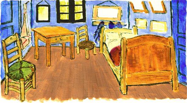
| rendering of van Gogh painting with Impasto |
3
example(s) -- impasto
IMPaSTo
is a realistic, interactive model for paint.
It allows the user to create images in the style
of famous painters as in the example above,
which is after a painting of van Gogh.
The impasto system implements a physical model
of paint to simulate the effect of acrylic
or oilpaint, using Cg shaders for real-time rendering, [Impasto].
research directions -- the art of shader programming
At first sight, shader programming seems to be an esoteric endeavor.
However, as already indicated in this section, there
are a number of high level languages for shader programming,
including NVIDIA Cg and Microsoft HLSL.
Cg is a platform independent language, suitable for both
OpenGL and Direct3D.
However, counter to what you might expect also Microsoft
HLSL can be used for the OpenGL platform when you choose
the proper runtime support.
To support the development of shaders
there are, apart from a number of books, some
powerful tools to write and test your shaders,
in particular the already mentioned ATI Rendermonkey tool,
the CgFx tool, which both produce HLSL code,
as well as the Cg viewer and the effect tool that comes
with the Microsoft DirectX 9 SDK.
Although I am only a beginning shader programmer myself,
I find it truly amazing what shaders can do.
For a good introducion I advice [Cg].
Futher you may consult [Shader1], [Shader2] and [Shader3].
Written from an artist's perspective is [ShaderArt].
(C) Æliens
04/09/2009
You may not copy or print any of this material without explicit permission of the author or the publisher.
In case of other copyright issues, contact the author.
