Cylinder {
field SFBool bottom TRUE
field SFFloat height 2 # (0, )
field SFFloat radius 1 # (0,
 )
field SFBool side TRUE
field SFBool top TRUE
}
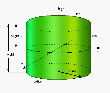
The Cylinder node specifies a capped cylinder centred at (0,0,0) in
the local coordinate system and with a central axis oriented along the
local Y-axis. By default, the cylinder is sized at "-1" to "+1" in all
three dimensions. The radius field specifies the radius of the
cylinder and the height field specifies the height of the cylinder
along the central axis. Both radius and height shall be
greater than 0.0. Figure 3.13 illustrates the Cylinder node.
The cylinder has three parts: the side, the top
(Y = +height/2) and the bottom (Y = -height/2).
Each part has an associated SFBool field that indicates whether the
part exists (TRUE) or does not exist (FALSE). Parts which do not exist
are not rendered and not eligible for intersection tests (e.g., collision
detection or sensor activation).

Figure 3-13: Cylinder node
When a texture is applied to a cylinder, it is applied differently
to the sides, top, and bottom. On the sides, the texture wraps counterclockwise
(from above) starting at the back of the cylinder. The texture has a
vertical seam at the back, intersecting the X=0 plane. For the top and
bottom caps, a circle is cut out of the unit texture squares centred
at (0, +/- height/2, 0) with dimensions 2 × radius
by 2 × radius. The top texture appears right side
up when the top of the cylinder is tilted toward the +Z-axis, and the
bottom texture appears right side up when the top of the cylinder is
tilted toward the -Z-axis. TextureTransform
affects the texture coordinates of the Cylinder node.
The Cylinder node's geometry requires outside faces only. When viewed
from the inside the results are undefined.
| TECHNICAL
NOTE: Cylinder
nodes are specified in the geometry field of a Shape node;
they may not be children of a Transform or Group node. VRML 1.0
allowed the application of separate materials to each of the parts
of the cylinder. That feature was removed because it was rarely
used and because removing it simplified both the Cylinder node
and the Material node (which was constrained to containing only
one material definition). To accomplish the equivalent functionality
with VRML 2.0, you must define three separate cylinder shapes,
each with a different part and a different material. This is a
more general mechanism, allowing each part to have a different
texture or material. |
|
EXAMPLE
(click to run): The
following example illustrates use of the Cylinder node (see
Figure 3-14). Note the default orientation of the texture map
on the cylinder sides and caps:
#VRML V2.0 utf8
Group { children [
  DEF C1 Shape {
    appearance Appearance {
      material DEF M1 Material {
        diffuseColor 1 1 1
        specularColor 1 1 1
        shininess .9
      texture ImageTexture { url "marble2.gif" }
    }
    geometry Cylinder { radius 1  height 5.0 }
  }
  Transform {
    translation 0 1 0
    rotation 0 0 1 1.571
    children Shape {
      appearance DEF A1 Appearance { material USE M1 }
      geometry Cylinder { radius 0.5 height 4.0 }
    }
  }
  Transform {
    translation 0 -2.5 0
    children DEF C2 Shape {
      appearance USE A1
      geometry Cylinder { radius 1.5 height 0.5 }
    }
  }
  Transform {
    translation 0 1 0
    rotation 0 0 1 1.571
    scale 0.25 1.5 1
    children USE C1
  }
  Transform {
    translation 0 2.5 0
    scale 0.75 0.5 0.75
    children USE C2
  }
  Background { skyColor 1 1 1 }
  NavigationInfo { type "EXAMINE" }
]}
|

