IndexedLineSet {
eventIn MFInt32 set_colorIndex
eventIn MFInt32 set_coordIndex
exposedField SFNode color NULL
exposedField SFNode coord NULL
field MFInt32 colorIndex [] # [-1, )
field SFBool colorPerVertex TRUE
field MFInt32 coordIndex [] # [-1,)
}
)
field SFBool colorPerVertex TRUE
field MFInt32 coordIndex [] # [-1,)
}
The IndexedLineSet node represents a 3D geometry formed by constructing
polylines from 3D vertices specified in the coord field.
IndexedLineSet uses the indices in its coordIndex field to
specify the polylines by connecting vertices from the coord
field. An index of "-1" indicates that the current polyline
has ended and the next one begins. The last polyline may be (but does
not have to be) followed by a "-1". IndexedLineSet is
specified in the local coordinate system and is affected by ancestors'
transformations.
The coord field specifies the 3D vertices of the line set and
contains a Coordinate node.
Lines are not lit, are not texture-mapped, and do not participate in
collision detection. The width of lines is implementation dependent and
each line segment is solid (i.e., not dashed).
If the color field is not NULL, it shall contain a Color node,
and the colours are applied to the line(s) as follows:
-
If colorPerVertex is FALSE:
-
If the colorIndex field is not empty, then one colour is
used for each polyline of the IndexedLineSet. There must be at least as
many indices in the colorIndex field as there are
polylines in the IndexedLineSet. If the greatest index in the colorIndex
field is N, then there must be N+1 colours in the Color node. The colorIndex
field must not contain any negative entries.
-
If the colorIndex field is empty, then the colours from
the Color node are applied to each polyline of the IndexedLineSet in
order. There must be at least as many colours in the Color node as
there are polylines.
-
If colorPerVertex is TRUE:
-
If the colorIndex field is not empty, then colours are
applied to each vertex of the IndexedLineSet in exactly the same manner
that the coordIndex field is used to supply coordinates
for each vertex from the Coordinate node. The colorIndex
field must contain at least as many indices as the coordIndex
field and must contain end-of-polyline markers (-1) in exactly the
same places as the coordIndex field. If the greatest
index in the colorIndex field is N, then there must be
N+1 colours in the Color node.
-
If the colorIndex field is empty, then the coordIndex
field is used to choose colours from the Color node. If the greatest
index in the coordIndex field is N, then there must be
N+1 colours in the Color node.
If the color field is NULL and there is a Material defined for
the Appearance affecting this IndexedLineSet, the emissiveColor
of the Material shall be used to draw the lines. Details on lighting
equations as they affect IndexedLineSet nodes are described in "2.14 Lighting model."
tip
IndexedLineSet nodes are specified in the geometry field of
Shape nodes.
design note
IndexedFaceSet, IndexedLineSet, and PointSet are the three fundamental
geometry primitives that support drawing of polygons, lines, and
points. Points and lines are not textured or lit. Some rendering
libraries support texture mapping or lighting points and lines, but
adding support for texture coordinates and normals to IndexedLineSet
and PointSet would add complexity for a seldom-used feature.
The following example illustrates typical use of the IndexedLineSet.
Note that the first IndexedLineSet applies colors per polyline (one for
the axes and one for the center line) and the second IndexedLineSet
applies colors per vertex using the indices specified in the coordIndex
(default):
#VRML V2.0 utf8
Transform { children [
  Shape {
    geometry IndexedLineSet {
      point [ 0 10 0, 0 0 0, 20 0 0, -1 5 0, 21 5 0 ]
      coordIndex [ 0 1 2 -1   # axes
                   3 4 ]      # centerline
      color Color { color [ 0 0 0, .2 .2 .2 ] }
      colorIndex [ 0 1 ]      # black for axes, gray for centerline
      colorPerVertex FALSE    # color per polyline
    }
  }
  Shape {
    geometry IndexedLineSet {
      point [ 2 1 0, 5 2 0, 8 1.5 0, 11 9 0, 14 7 0, 17 10 0 ]
      coordIndex [ 0 1 2 3 4 5 ]     # connect the dots
      color Color { color [ .1 .1 .1, .2 .2 .2, .15 .15 .15,
                            .9 .9 .9 , .7 .7 .7, 1 1 1  ] }
  }
]}  # end of children and Transform
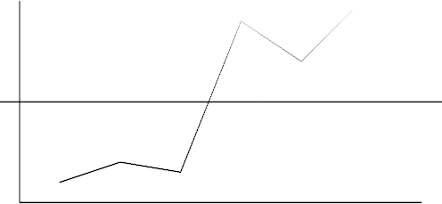
Figure 3-34: IndexedLineSet Node Example