SphereSensor {
exposedField SFBool autoOffset TRUE
exposedField SFBool enabled TRUE
exposedField SFRotation offset 0 1 0 0 # [-1,1],(- ,
, )
eventOut SFBool isActive
eventOut SFRotation rotation_changed
eventOut SFVec3f trackPoint_changed
}
The SphereSensor node maps pointing device motion into spherical rotation
about the origin of the local coordinate system. The SphereSensor node
uses the descendent geometry of its parent node to determine whether
it is liable to generate events.
The enabled exposed field enables and disables the SphereSensor
node. If enabled is TRUE, the sensor reacts appropriately to
user events. If enabled is FALSE, the sensor does not track user
input or send events. If enabled receives a FALSE event and isActive
is TRUE, the sensor becomes disabled and deactivated, and outputs an
isActive FALSE event. If enabled receives a TRUE event
the sensor is enabled and ready for user activation.
The SphereSensor node generates events when the pointing device is
activated while the pointer is indicating any descendent geometry nodes
of the sensor's parent group. See "2.6.7.5
Activating and manipulating sensors" for details on using the pointing
device to activate the SphereSensor.
Upon activation of the pointing device (e.g., mouse button down)
over the sensor's geometry, an isActive TRUE event is sent. The
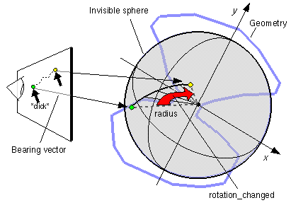
vector defined by the initial point of intersection on the SphereSensor's
geometry and the local origin determines the radius of the sphere that
is used to map subsequent pointing device motion while dragging. The
virtual sphere defined by this radius and the local origin at the time
of activation is used to interpret subsequent pointing device motion
and is not affected by any changes to the sensor's coordinate system
while the sensor is active. For each position of the bearing, a rotation_changed
event is sent which corresponds to the sum of the relative rotation
from the original intersection point plus the offset value. trackPoint_changed
events reflect the unclamped drag position on the surface of this sphere.
When the pointing device is deactivated and autoOffset is TRUE,
offset is set to the last rotation_changed value and an
offset_changed event is generated. "2.6.7.4 Drag sensors" provides more details.
When the sensor generates an isActive TRUE event, it grabs
all further motion events from the pointing device until it is released
and generates an isActive FALSE event (other pointing-device
sensors cannot generate events during this time). Motion of the
pointing device while isActive is TRUE is termed a "drag". If
a 2D pointing device is in use, isActive events will typically
reflect the state of the primary button associated with the device (i.e., isActive
is TRUE when the primary button is pressed and FALSE when it is released).
If a 3D pointing device (e.g., wand) is in use, isActive
events will typically reflect whether the pointer is within (or in contact
with) the sensor's geometry.

Figure 3-51: SphereSensor node
While the pointing device is activated, trackPoint_changed
and rotation_changed events are output. trackPoint_changed
events represent the unclamped intersection points on the surface of
the invisible sphere. If the pointing device is dragged off the sphere
while activated, browsers may interpret this in a variety of ways (e.g.,
clamp all values to the sphere or continue to rotate as the point is
dragged away from the sphere). Each movement of the pointing device
while isActive is TRUE generates trackPoint_changed and
rotation_changed events.
Further information about this behaviour may be found in "2.6.7.3 Pointing-device sensors", "2.6.7.4
Drag sensors", and "2.6.7.5 Activating
and manipulating sensors."

