The Annotated VRML 97 Reference

1 Intro     Concepts     3 Nodes     4 Fields/Events    Conformance
A Grammar     B Java     C JavaScript     D Examples     E Related Info    References
Quick Java         Quick JavaScript         Quick Nodes   
 

  About the Book
  
Help
  Copyright © 1997-99
  Purchase the book from Amazon.com

Chapter 3:
Node Reference


Intro
Anchor
Appearance
AudioClip
Background
Billboard
Box
Collision
Color
ColorInterpolator
Cone
Coordinate
CoordinateInterpolator
Cylinder
CylinderSensor
DirectionalLight
ElevationGrid
Extrusion
Fog
FontStyle
Group
ImageTexture
IndexedFaceSet
IndexedLineSet
Inline
LOD
Material
MovieTexture
NavigationInfo
Normal
NormalInterpolator
OrientationInterpolator
PixelTexture
PlaneSensor
PointLight
PointSet
PositionInterpolator
ProximitySensor
ScalarInterpolator
Script
Shape
Sound
Sphere
SphereSensor
SpotLight
Switch
Text
TextureCoordinate
TextureTransform
TimeSensor
TouchSensor
Transform
Viewpoint
VisibilitySensor
WorldInfo

+3.15 CylinderSensor

CylinderSensor { 
  exposedField SFBool     autoOffset TRUE
  exposedField SFFloat    diskAngle  0.262   # (0,PI/2)
  exposedField SFBool     enabled    TRUE
  exposedField SFFloat    maxAngle   -1      # [-2PI,2PI]
  exposedField SFFloat    minAngle   0       # [-2PI,2PI]
  exposedField SFFloat    offset     0       # (-INF,INF)
  eventOut     SFBool     isActive
  eventOut     SFRotation rotation_changed
  eventOut     SFVec3f    trackPoint_changed
}

The CylinderSensor node maps pointer motion (e.g., a mouse or wand) into a rotation on an invisible cylinder that is aligned with the Y-axis of the local coordinate system. The CylinderSensor uses the descendent geometry of its parent node to determine whether it is liable to generate events.

The enabled exposed field enables and disables the CylinderSensor node. If TRUE, the sensor reacts appropriately to user events. If FALSE, the sensor does not track user input or send events. If enabled receives a FALSE event and isActive is TRUE, the sensor becomes disabled and deactivated, and outputs an isActive FALSE event. If enabled receives a TRUE event the sensor is enabled and ready for user activation.

A CylinderSensor node generates events when the pointing device is activated while the pointer is indicating any descendent geometry nodes of the sensor's parent group. See "2.6.7.5 Activating and manipulating sensors" for more details on using the pointing device to activate the CylinderSensor.

Upon activation of the pointing device while indicating the sensor's geometry, an isActive TRUE event is sent. The initial acute angle between the bearing vector and the local Y-axis of the CylinderSensor node determines whether the sides of the invisible cylinder or the caps (disks) are used for manipulation. If the initial angle is less than the diskAngle, the geometry is treated as an infinitely large disk lying in the local Y=0 plane and coincident with the initial intersection point. Dragging motion is mapped into a rotation around the local +Y-axis vector of the sensor's coordinate system. The perpendicular vector from the initial intersection point to the Y-axis defines zero rotation about the Y-axis. For each subsequent position of the bearing, a rotation_changed event is sent that equals the sum of the rotation about the +Y-axis vector (from the initial intersection to the new intersection) plus the offset value. trackPoint_changed events reflect the unclamped drag position on the surface of this disk. When the pointing device is deactivated and autoOffset is TRUE, offset is set to the last value of rotation_changed and an offset_changed event is generated. Section "2.6.7.4 Drag sensors" provides a more general description of autoOffset and offset_changed.

CylinderSensor node: angle < diskAngle

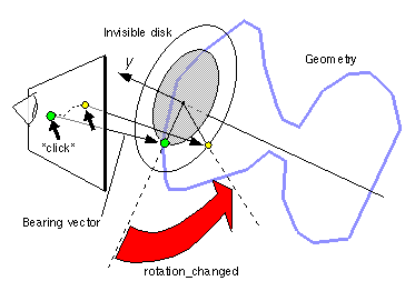
Figure 3-16: CylinderSensor Node: Bearing Angle < diskAngle

If the initial acute angle between the bearing vector and the local Y-axis of the CylinderSensor node is greater than or equal to diskAngle, then the sensor behaves like a cylinder. The shortest distance between the point of intersection (between the bearing and the sensor's geometry) and the Y-axis of the parent group's local coordinate system determines the radius of an invisible cylinder used to map pointing device motion and marks the zero rotation value. For each subsequent position of the bearing, a rotation_changed event is sent that equals the sum of the right-handed rotation from the original intersection about the +Y-axis vector plus the offset value. trackPoint_changed events reflect the unclamped drag position on the surface of the invisible cylinder. When the pointing device is deactivated and autoOffset is TRUE, offset is set to the last rotation angle and an offset_changed event is generated. More details are available in "2.6.7.4 Drag sensors."

CylinderSensor node: angle >= diskAngle

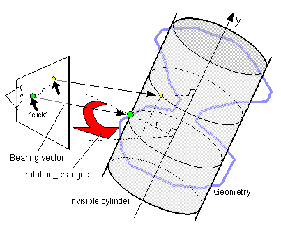
Figure 3-15: CylinderSensor Node: Bearing Angle >= diskAngle

When the sensor generates an isActive TRUE event, it grabs all further motion events from the pointing device until it is released and generates an isActive FALSE event (other pointing-device sensors cannot generate events during this time). Motion of the pointing device while isActive is TRUE is referred to as a "drag." If a 2D pointing device is in use, isActive events will typically reflect the state of the primary button associated with the device (i.e., isActive is TRUE when the primary button is pressed and FALSE when it is released). If a 3D pointing device (e.g., a wand) is in use, isActive events will typically reflect whether the pointer is within or in contact with the sensor's geometry.

While the pointing device is activated, trackPoint_changed and rotation_changed events are output and are interpreted from pointing device motion based on the sensor's local coordinate system at the time of activation. trackPoint_changed events represent the unclamped intersection points on the surface of the invisible cylinder or disk. If the initial angle results in cylinder rotation (as opposed to disk behaviour) and if the pointing device is dragged off the cylinder while activated, browsers may interpret this in a variety of ways (e.g. clamp all values to the cylinder and continuing to rotate as the point is dragged away from the cylinder). Each movement of the pointing device while isActive is TRUE generates trackPoint_changed and rotation_changed events.

The minAngle and maxAngle fields clamp rotation_changed events to a range of values. If minAngle is greater than maxAngle, rotation_changed events are not clamped. The minAngle and maxAngle fields are restricted to the range [-2PI, 2PI].

Further information about this behaviour may be found in "2.6.7.3 Pointing-device sensors", "2.6.7.4 Drag sensors", and "2.6.7.5 Activating and manipulating sensors."

TIP: It is usually a bad idea to route a drag sensor to its own parent. Typically, the drag sensor will route to a Transform, which does not affect the sensor. See the following examples.

TECHNICAL NOTE: SphereSensor and CylinderSensor map the 2D motions of a mouse (or other pointing device) into 3D rotations. CylinderSensor constrains the rotation to a single axis, while SphereSensor allows arbitrary rotation. A CylinderSensor is not useful by itself; you must also specify some geometry to act as the "knob" and must do something with the rotation_changed events. Usually, the geometry will be put into a Transform node and the rotation_changed events will be sent to the Transform's set_rotation eventIn, so that the geometry rotates as the user manipulates the CylinderSensor. For example:
     #VRML V2.0 utf8 
     Group { children [ 
       DEF CS CylinderSensor { } 
       DEF T Transform { 
         children Shape { 
           appearance Appearance {
             material Material { }
           } 
           geometry Cylinder { } 
         } 
       } 
     ]} 
     ROUTE CS.rotation_changed TO T.set_rotation 

Typically the rotation_changed will also be routed to a Script that extracts the rotation angle, scales it appropriately, and uses it to control something else (the intensity of a Sound node in a virtual radio, perhaps). Adding an angle_changed SFFloat eventOut to give just the angle was considered, but extracting the angle from a rotation in a Script is easy, and a Script is necessary in most cases to perform the appropriate offset and scaling anyway.

An earlier design made CylinderSensor a grouping node that acted as a "smart Transform" that modified itself when the user interacted with it. That design was dropped because it was less flexible. Separating what causes the sensor to activate (its sibling geometry) from its effects on the scene (to what it is routed) adds capabilities without adding complexity to the VRML specification. For example, if you want to quantize a CylinderSensor so that it only rotates in five-degree increments, you can ROUTE the rotation_changed events to a Script that quantizes them and ROUTE the results to the Transform's set_rotation (and to anything else that would otherwise be routed from rotation_changed).

Originally, CylinderSensor was two nodes: CylinderSensor and DiskSensor. They were combined by introducing the diskAngle field. The problem with the original design was a singularity caused by the 2D-to-3D mapping. If the user was viewing the sensors nearly edge on, the rotation calculations became inaccurate and interaction suffered. By combining the two sensors into one and switching from one behavior to another, good interaction is maintained no matter what the relationship between the viewer and the sensor.

Setting diskAngle to extreme values results in purely cylindrical or disk behavior, identical to the original nodes. A disk angle of 0 degrees will result in disk interaction behavior no matter what the angle between the viewer and the axis of rotation. A disk angle of 90 degrees or greater (p/2 radians or greater) will force cylindrical behavior. The default was determined by trial and error to be a reasonable value. It corresponds to 15 degrees, resulting in cylindrical interaction when viewed from the sides and disk interaction when viewed from the top or bottom.


EXAMPLE (click to run): The following example illustrates the use of the CylinderSensor node (see Figure 3-17).
#VRML V2.0 utf8
Group { children [
  # The target object to be rotated needs
  # four Transforms. Two are used to orient the local
  # coord system, and two are used as the targets for
  # the sensors (T1 & T2).
  DEF T1 Transform { children
    Transform { rotation 0 0 1 -1.57 children
      DEF T2 Transform { children
        Transform { rotation 0 0 1 1.57 children
          Shape {
            appearance DEF A1 Appearance {
              material Material { diffuseColor 1 1 1 }
            }
            geometry Cone { bottomRadius 2 height 4 }
  }}}}}
  Transform {     # Left crank geometry
    translation -1 0 3
    rotation 0 0 1 -1.57
    children [
      DEF T3 Transform { children
        DEF G1 Group { children [
          Transform {
            rotation 0 0 1 1.57
            translation -.5 0 0
            children Shape {
              appearance USE A1
              geometry Cylinder { radius .1 height 1 }
            }
          }
          Transform {
            rotation 0 0 1 1.57
            translation -1 0 0
            children Shape {
              geometry Sphere { radius .2 }
              appearance USE A1
            }
          }
        ]} # end Group
      }
      DEF CS1 CylinderSensor { # Sensor for Left crank
        maxAngle 1.57          #  rotates Y axis => T1
        minAngle 0           
      }
    ]
  }
  Transform {     # Right crank geometry
    translation 1 0 3
    rotation 0 0 1 -1.57
    children [
      DEF T4 Transform { children USE G1 }
      DEF CS2 CylinderSensor { # Sensor for Right crank2
        maxAngle 1.57          #  rotates X-axis => T
        minAngle 0           
      }
    ]
  }
  Transform {                  # Housing to hold cranks
    translation 0 0 3
    children Shape {
      geometry Box { size 3 0.5 0.5 }
      appearance USE A1
    }
  }
  Background { skyColor 1 1 1 }
]}
ROUTE CS1.rotation_changed TO T1.rotation # rots Y-axis
ROUTE CS1.rotation_changed TO T3.rotation # rots L crank
ROUTE CS2.rotation_changed TO T2.rotation # rots X-axis
ROUTE CS2.rotation_changed TO T4.rotation # rots R crank


CylinderSensor node example

Figure 3-17: CylinderSensor Node Example