The Annotated VRML 97 Reference

1 Intro     Concepts     3 Nodes     4 Fields/Events    Conformance
A Grammar     B Java     C JavaScript     D Examples     E Related Info    References
Quick Java         Quick JavaScript         Quick Nodes   
 

  About the Book
  
Help
  Copyright © 1997-99
  Purchase the book from Amazon.com

Chapter 3:
Node Reference


Intro
Anchor
Appearance
AudioClip
Background
Billboard
Box
Collision
Color
ColorInterpolator
Cone
Coordinate
CoordinateInterpolator
Cylinder
CylinderSensor
DirectionalLight
ElevationGrid
Extrusion
Fog
FontStyle
Group
ImageTexture
IndexedFaceSet
IndexedLineSet
Inline
LOD
Material
MovieTexture
NavigationInfo
Normal
NormalInterpolator
OrientationInterpolator
PixelTexture
PlaneSensor
PointLight
PointSet
PositionInterpolator
ProximitySensor
ScalarInterpolator
Script
Shape
Sound
Sphere
SphereSensor
SpotLight
Switch
Text
TextureCoordinate
TextureTransform
TimeSensor
TouchSensor
Transform
Viewpoint
VisibilitySensor
WorldInfo

+3.45 SpotLight

SpotLight {
  exposedField SFFloat ambientIntensity 0         # [0,1]
  exposedField SFVec3f attenuation      1 0 0     # [0,INF)
  exposedField SFFloat beamWidth        1.570796  # (0,PI/2]
  exposedFeld SFColor  color            1 1 1     # [0,1]
  exposedFeld SFFloat  cutOffAngle      0.785398  # (0,PI/2]
  exposedFeld SFVec3f  direction        0 0 -1    # (-INF,INF)
  exposedFeld SFFloat  intensity        1         # [0,1]
  exposedFeld SFVec3f  location         0 0 0     # (-INF,INF)
  exposedFeld SFBool   on               TRUE
  exposedField SFFloat radius           100       # [0,INF)
}

The SpotLight node defines a light source that emits light from a specific point along a specific direction vector and constrained within a solid angle. Spotlights may illuminate geometry nodes that respond to light sources and intersect the solid angle defined by the SpotLight. Spotlight nodes are specified in the local coordinate system and are affected by ancestors' transformations.

A detailed description of ambientIntensity, color, intensity, and VRML's lighting equations is provided in "2.6.6 Light sources." More information on lighting concepts can be found in "2.14 Lighting model" including a detailed description of the VRML lighting equations.

The location field specifies a translation offset of the centre point of the light source from the light's local coordinate system origin. This point is the apex of the solid angle which bounds light emission from the given light source. The direction field specifies the direction vector of the light's central axis defined in the local coordinate system.

The on field specifies whether the light source emits light. If on is TRUE, the light source is emitting light and may illuminate geometry in the scene. If on is FALSE, the light source does not emit light and does not illuminate any geometry.

The radius field specifies the radial extent of the solid angle and the maximum distance from location that may be illuminated by the light source. The light source does not emit light outside this radius. The radius shall be >= 0.0.

Both radius and location are affected by ancestors' transformations (scales affect radius and transformations affect location).

The cutOffAngle field specifies the outer bound of the solid angle. The light source does not emit light outside of this solid angle. The beamWidth field specifies an inner solid angle in which the light source emits light at uniform full intensity. The light source's emission intensity drops off from the inner solid angle (beamWidth) to the outer solid angle (cutOffAngle) as described in the following equations:

    angle = the angle between the Spotlight's direction vector
            and the vector from the Spotlight loc to the point
            to be illuminated

    if (angle >= cutOffAngle):
        multiplier = 0
    else if (angle <= beamWidth):
        multiplier = 1
    else:
        multiplier = (angle - cutOffAngle)
                          / (beamWidth - cutOffAngle)

    intensity(angle) = SpotLight.intensity × multiplier

If the beamWidth is greater than the cutOffAngle, beamWidth is defined to be equal to the cutOffAngle and the light source emits full intensity within the entire solid angle defined by cutOffAngle. Both beamWidth and cutOffAngle shall be greater than 0.0 and less than or equal to PI/2. Figure 3.16 depicts the beamWidth, cutOffAngle, direction, location, and radius fields of the SpotLight node.
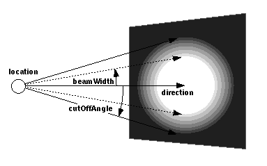
SpotLight node

Figure 3-53: SpotLight node

TIP: Typically, beamWidth > cutOffAngle will produce faster rendering (and "harder" spotlight effects) than beamWidth < cutOffAngle. Also, note that some implementations ignore beamWidth. It is recommended that you test this feature on your intended browser before using it.

TECHNICAL NOTE: The default beamWidth (1.570796 radians) was chosen to be greater than the default cutOffAngle (0.785398 radians) for performance reasons. If beamWidth is less than the cutOffAngle, the lighting equations must perform extra calculations (i.e., cosine drop-off) and will slow down rendering. The default field values were chosen so that the default SpotLights render as fast as possible, and if the author sets cutOffAngle (and not beamWidth), the SpotLight continues to render quickly without beamWidth performance impacts.

SpotLight illumination falls off with distance as specified by three attenuation coefficients. The attenuation factor is 1/max(attenuation[0] + attenuation[1]×r + attenuation[2]×r2, 1), where r is the distance from the light to the surface being illuminated. The default is no attenuation. An attenuation value of (0, 0, 0) is identical to (1, 0, 0). Attenuation values must be >= 0.0. A detailed description of VRML's lighting equations is contained in "2.14 Lighting model."

TIP: In order to produce soft penumbras, it will be necessary to generate a large number of vertices in the geometry (remember that lighting calculations are typically performed only at the vertices!). This can have the undesirable effect of slowing rendering and increasing download time. For faster rendering performance, in cases where the light source is not moving, consider using an ImageTexture with lighting effects "painted" on, rather than render the effect at each frame.

TIP: The radius field of PointLight and SpotLight restricts the illumination effects of these light sources. It is recommended that you minimize this field to the smallest possible value (i.e., small enough to enclose all of the Shapes that you intend to illuminate) in order to avoid significant impacts on rendering performance. A safe rule to live by is: "Never create a file in which the radius fields of the light sources exceed the bounding box enclosing all the Shapes in the file." This has the nice property that prevents light sources from bleeding outside of the original file. Keep in mind that, during rendering, each Shape must perform lighting calculations at each vertex for each light source that affects it. Thus, restricting each light source to the intended radius can improve performance and create files that will compose nicely.

TIP: See the DirectionalLight section in this chapter for general tips on light sources.

EXAMPLE (click to run): The following example illustrates the SpotLight node (see Figure 3-54). This file contains three SpotLights. The first, L1, is directed at the Sphere; the second, L2, is directed at a corner of the Box; and the third, L3, is directed at the Cone. Notice the amount of vertices that the ElevationGrid required to produce a soft penumbra effect:

#VRML V2.0 utf8
Group { children [
  DEF L1 SpotLight {
    location 0.0 3.8 3
    direction 0.035 -0.84 -0.55
    beamWidth 0.017
    cutOffAngle 1.5708
  }
  DEF L2 SpotLight {
    location -3 3.4 2.6
    direction 0.06 -0.85 -0.51
    beamWidth 0.017
    cutOffAngle 1.5708
  }
  DEF L3 SpotLight {
    location 2.2 4 2
    direction 0.34 -0.91 -0.24
    beamWidth 0.017
    cutOffAngle 1.5708
  }
  Transform {
    translation -3 0.77 0
    rotation 0.301025 0.943212 -0.140478  0.93
    scale 0.85 0.85 0.85
    scaleOrientation -0.317855 0.939537 -0.127429
                      0.960173
    children Shape {
      appearance DEF A1 Appearance {
        material Material {
          ambientIntensity .5
          diffuseColor 0.85 0.85 0.85
          specularColor 1 1 1
          shininess 0.56
        }
      }
      geometry Box {}
    }
  }
  Transform {
    translation 0 0.7 0
    children Shape {
      appearance USE A1
      geometry Sphere {}
    }
  }
  Transform {
    translation 3 1.05 0
    rotation 0 0 1 0.6
    children Shape {
      appearance USE A1
      geometry Cone {}
    }
  }
  Transform {
    translation -2.71582 -1 -0.785248
    children Shape {
      appearance USE A1
      geometry ElevationGrid {
        height [ 0, 0, 0, 0, ..., 0 ]
        xDimension 20
        xSpacing 0.2
        zDimension 10
        zSpacing 0.1
      }
    }
  }
  Background { skyColor 1 1 1 }
  NavigationInfo { headlight FALSE type "EXAMINE" }
]} 
 

SpotLight node example

Figure 3-54: SpotLight Node Exampl