|
Chapter 3:
Node Reference
Intro
Anchor
Appearance
AudioClip
Background
Billboard
Box
Collision
Color
ColorInterpolator
Cone
Coordinate
CoordinateInterpolator
Cylinder
CylinderSensor
DirectionalLight
ElevationGrid
Extrusion
Fog
FontStyle
Group
ImageTexture
IndexedFaceSet
IndexedLineSet
Inline
LOD
Material
MovieTexture
NavigationInfo
Normal
NormalInterpolator
OrientationInterpolator
PixelTexture
PlaneSensor
PointLight
PointSet
PositionInterpolator
ProximitySensor
ScalarInterpolator
Script
Shape
Sound
Sphere
SphereSensor
SpotLight
Switch
Text
TextureCoordinate
TextureTransform
TimeSensor
TouchSensor
Transform
Viewpoint
VisibilitySensor
WorldInfo
|
IndexedFaceSet {
eventIn MFInt32 set_colorIndex
eventIn MFInt32 set_coordIndex
eventIn MFInt32 set_normalIndex
eventIn MFInt32 set_texCoordIndex
exposedField SFNode color NULL
exposedField SFNode coord NULL
exposedField SFNode normal NULL
exposedField SFNode texCoord NULL
field SFBool ccw TRUE
field MFInt32 colorIndex [] # [-1, )
field SFBool colorPerVertex TRUE
field SFBool convex TRUE
field MFInt32 coordIndex [] # [-1, )
field SFBool colorPerVertex TRUE
field SFBool convex TRUE
field MFInt32 coordIndex [] # [-1, )
field SFFloat creaseAngle 0 # [0, )
field SFFloat creaseAngle 0 # [0, )
field MFInt32 normalIndex [] # [-1, )
field MFInt32 normalIndex [] # [-1, )
field SFBool normalPerVertex TRUE field SFBool solid TRUE
field MFInt32 texCoordIndex [] # [-1, )
field SFBool normalPerVertex TRUE field SFBool solid TRUE
field MFInt32 texCoordIndex [] # [-1, )
} )
}
The IndexedFaceSet node represents a 3D shape formed by constructing
faces (polygons) from vertices listed in the coord field. The
coord field contains a Coordinate node that defines the 3D vertices
referenced by the coordIndex field. IndexedFaceSet uses the indices
in its coordIndex field to specify the polygonal faces by indexing
into the coordinates in the Coordinate node. An index of "-1" indicates
that the current face has ended and the next one begins. The last face
may be (but does not have to be) followed by a "-1" index. If the greatest
index in the coordIndex field is N, the Coordinate node shall
contain N+1 coordinates (indexed as 0 to N). Each face of the IndexedFaceSet
shall have:
- at least three non-coincident vertices,
- vertices that define a planar polygon,
- vertices that define a non-self-intersecting polygon.
Otherwise, results are undefined.
The IndexedFaceSet node is specified in the local coordinate system
and is affected by ancestors' transformations.
|
TIP:
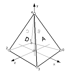
Figure 3-31 illustrates the structure of the following simple
IndexedFaceSet:
IndexedFaceSet {
   coord Coordinate {
     point [ 1 0 -1, -1 0 -1, -1 0 1, 1 0 1, 0 2 0 ]
   }
   coordIndex [ 0 4 3 -1   # face A, right
                1 4 0 -1   # face B, back
                2 4 1 -1   # face C, left
                3 4 2 -1   # face D, front
                0 3 2  1 ] # face E, bottom
}
|

Figure 3-31: IndexedFaceSet Node
Descriptions of the coord, normal, and texCoord
fields are provided in the Coordinate, Normal, and TextureCoordinate
nodes, respectively.
Details on lighting equations and the interaction between color
field, normal field, textures, materials, and geometries are
provided in "2.14 Lighting model".
If the color field is not NULL, it must contain a Color node
whose colours are applied to the vertices or faces of the IndexedFaceSet
as follows:
- If colorPerVertex is FALSE, colours are applied to each
face, as follows:
- If the colorIndex field is not empty, then one colour
is used for each face of the IndexedFaceSet. There must be at
least as many indices in the colorIndex field as there
are faces in the IndexedFaceSet. If the greatest index in the
colorIndex field is N, then there must be N+1 colours in
the Color node. The colorIndex field must not contain any
negative entries.
- If the colorIndex field is empty, then the colours in
the Color node are applied to each face of the IndexedFaceSet
in order. There must be at least as many colours in the Color
node as there are faces.
- If colorPerVertex is TRUE, colours are applied to each vertex,
as follows:
- If the colorIndex field is not empty, then colours are
applied to each vertex of the IndexedFaceSet in exactly the same
manner that the coordIndex field is used to choose coordinates
for each vertex from the Coordinate node. The colorIndex
field must contain at least as many indices as the coordIndex
field, and must contain end-of-face markers (-1) in exactly the
same places as the coordIndex field. If the greatest index
in the colorIndex field is N, then there must be N+1 colours
in the Color node.
- If the colorIndex field is empty, then the coordIndex
field is used to choose colours from the Color node. If the greatest
index in the coordIndex field is N, then there must be
N+1 colours in the Color node.
If the color field is NULL, the geometry shall be rendered
normally using the Material and texture defined in the Appearance node
(see "2.14 Lighting model" for details).
If the normal field is not NULL, it must contain a Normal node
whose normals are applied to the vertices or faces of the IndexedFaceSet
in a manner exactly equivalent to that described above for applying
colours to vertices/faces (where normalPerVertex corresponds
to colorPerVertex and normalIndex corresponds to colorIndex).
If the normal field is NULL, the browser shall automatically
generate normals, using creaseAngle to determine if and how normals
are smoothed across shared vertices (see "2.6.3.5
Crease angle field").
If the texCoord field is not NULL, it must contain a TextureCoordinate node. The texture coordinates in that
node are applied to the vertices of the IndexedFaceSet as follows:
- If the texCoordIndex field is not empty, then it is used
to choose texture coordinates for each vertex of the IndexedFaceSet
in exactly the same manner that the coordIndex field is used
to choose coordinates for each vertex from the Coordinate node. The
texCoordIndex field must contain at least as many indices as
the coordIndex field, and must contain end-of-face markers
(-1) in exactly the same places as the coordIndex field. If
the greatest index in the texCoordIndex field is N, then there
must be N+1 texture coordinates in the TextureCoordinate node.
- If the texCoordIndex field is empty, then the coordIndex
array is used to choose texture coordinates from the TextureCoordinate
node. If the greatest index in the coordIndex field is N, then
there must be N+1 texture coordinates in the TextureCoordinate node.
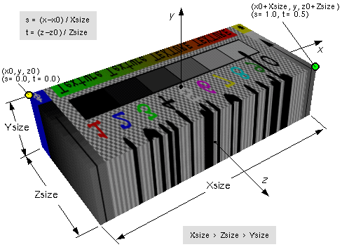
If the texCoord field is NULL, a default texture coordinate
mapping is calculated using the local coordinate system bounding box
of the shape. The longest dimension of the bounding box defines the
S coordinates, and the next longest defines the T coordinates. If two
or all three dimensions of the bounding box are equal, ties shall be
broken by choosing the X, Y, or Z dimension in that order of preference.
The value of the S coordinate ranges from 0 to 1, from one end of the
bounding box to the other. The T coordinate ranges between 0 and the
ratio of the second greatest dimension of the bounding box to the greatest
dimension. Figure 3-32 illustrates the
default texture coordinates for a simple box shaped IndexedFaceSet with
an X dimension twice as large as the Z dimension and four times as large
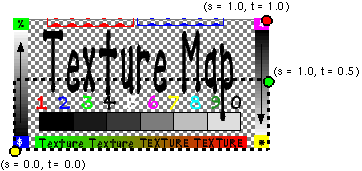
as the Y dimension. Figure 3-33 illustrates the original texture image
used on the IndexedFaceSet used in Figure 3-32.

Figure 3-32: IndexedFaceSet Texture Default Mapping

Figure 3-33: ImageTexture for IndexedFaceSet in
Figure 3-32
Section "2.6.3 Shapes and geometry"
provides a description of the ccw, solid, convex,
and creaseAngle fields.
|
TECHNICAL
NOTE: IndexedFaceSet nodes are specified in the geometry
field of Shape nodes. Unlike VRML 1.0, they cannot be added directly
as children of grouping nodes; a Shape must be used to associate
an appearance (material and texture) with each IndexedFaceSet.
Most geometry
in most VRML worlds is made of IndexedFaceSets. In fact, most
of the other geometry nodes in VRML (Extrusion, ElevationGrid,
Cube, Cone, Sphere, and Cylinder) could be implemented as prototyped
IndexedFaceSets with Scripts that generated the appropriate geometry.
Vertex positions,
colors, normals, and texture coordinates are all specified as
separate nodes (stored in the coord, color, normal,
and texCoord exposedFields) to allow them to be shared
between different IndexedFaceSets. Sharing saves bandwidth and
can be very convenient. For example, you might create a model
with interior parts and wish to allow the user to control whether
the exterior or interior is being shown. You can put the interior
and exterior in two different Shapes underneath a Switch node,
but still share vertex coordinates between the interior and exterior
parts.
The default
texture coordinates generated by an IndexedFaceSet are easy to
calculate and are well defined, but otherwise have very little
to recommend them. If you are texturing an IndexedFaceSet that
is anything more complicated than a square, you will almost certainly
want to define better texture coordinates. Unfortunately, automatically
generating good texture coordinates for each vertex is very difficult,
and a good mapping depends on the texture image being used, whether
the IndexedFaceSet is part of a larger surface, and so on. A good
modeling system will provide both better automatic texture coordinate
generation and precise control over how texture images are wrapped
across each polygon.
Generating
good default normals is a much easier task, and by setting creaseAngle
appropriately you will almost always be able to get a good-looking
surface without bloating your files with explicit normals.
The *Index
fields are not fully exposed: You can only set them; you cannot
get them. This is done to help implementations that might convert
the IndexedFaceSet to a more efficient internal representation.
For example, some graphics hardware is optimized to draw triangular
strips. A browser running with such hardware might triangulate
the IndexedFaceSets given to it and create triangular strips when
the VRML file is read and whenever it receives a set_*Index
event. After doing so, it can free up the memory used by the index
arrays. If those arrays were exposedFields, a much more complicated
analysis would have to be done to determine whether or not their
values might possibly be accessed sometime in the future.
|
EXAMPLE
(click to run):
This example shows three IndexedFaceSets illustrating color applied
per face, indexed color applied per vertex, texture coordinates
applied per vertex, and a dodecahedron (20 vertices, 12 faces, 6
colors [primaries, RGB; complements, CMY]) mapped to the faces.
#VRML V2.0 utf8
Viewpoint { description "Initial view" position 0 0 9 }
NavigationInfo { type "EXAMINE" }
# Three IndexedFaceSets, showing:
#  - Color applied per-face, indexed
#  - Color applied per-vertex
#  - Texture coordinates applied per-vertex

# A dodecahedron: 20 vertices, 12 faces.
# 6 colors (primaries:RGB and complements:CMY) mapped to the faces.
Transform {
  translation -1.5 0 0
  children Shape {
    appearance DEF A Appearance { material Material { } }
    geometry DEF IFS IndexedFaceSet {
      coord Coordinate {
        point [ # Coords/indices derived from "Jim Blinn's Corner"
          1 1 1, 1 1 -1, 1 -1 1, 1 -1 -1,
          -1 1 1, -1 1 -1, -1 -1 1, -1 -1 -1,
          .618 1.618 0, -.618 1.618 0, .618 -1.618 0, -.618 -1.618 0,
          1.618 0 .618, 1.618 0 -.618, -1.618 0 .618, -1.618 0 -.618,
          0 .618 1.618, 0 -.618 1.618, 0 .618 -1.618, 0 -.618 -1.618
        ]
      }
      coordIndex [
        1 8 0 12 13 -1,  4 9 5 15 14 -1,  2 10 3 13 12 -1,
        7 11 6 14 15 -1, 2 12 0 16 17 -1,  1 13 3 19 18 -1,
        4 14 6 17 16 -1,  7 15 5 18 19 -1, 4 16 0 8 9 -1,
        2 17 6 11 10 -1,  1 18 5 9 8 -1,  7 19 3 10 11 -1,
      ]
      color Color {  # Six colors:
        color [ 0 0 1, 0 1 0, 0 1 1, 1 0 0, 1 0 1, 1 1 0 ]
      }
      colorPerVertex FALSE  # Applied to faces, not vertices
      # This indexing gives a nice symmetric appearance:
      colorIndex [ 0, 1, 1, 0, 2, 3, 3, 2, 4, 5, 5, 4 ]

      # Five texture coordinates, for the five vertices on each face.
      # These will be re-used by indexing into them appropriately.
      texCoord TextureCoordinate {
        point [  # These are the coordinates of a regular pentagon:
          0.654508 0.0244717,  0.0954915 0.206107
          0.0954915 0.793893,  0.654508 0.975528, 1 0.5,
        ]
      }
      # And this particular indexing makes a nice image:
      texCoordIndex [
        0 1 2 3 4 -1,  2 3 4 0 1 -1,  4 0 1 2 3 -1,  1 2 3 4 0 -1,
        2 3 4 0 1 -1,  0 1 2 3 4 -1,  1 2 3 4 0 -1,  4 0 1 2 3 -1,
        4 0 1 2 3 -1,  1 2 3 4 0 -1,  0 1 2 3 4 -1,  2 3 4 0 1 -1,
              ]
    }
  }
}
# A tetrahedron, with a color at each vertex:
Transform {
  translation 1.5 -1.5 0
  children Shape {
    appearance USE A  # Use same dflt material as dodecahedron
    geometry IndexedFaceSet {
      coord Coordinate {
        point [ # Coords/indices derived from "Jim Blinn's Corner"
          1 1 1, 1 -1 -1, -1 1 -1, -1 -1 1,
        ]
      }
      coordIndex [
        3 2 1 -1,  2 3 0 -1,  1 0 3 -1,  0 1 2 -1,
      ]
      color Color {  # Four colors:
        color [ 0 1 0, 1 1 1, 0 0 1, 1 0 0 ]
      }
      # Leave colorPerVertex field set to TRUE.
      # And no indices are needed, either-- each coordinate point
      # is assigned a color (or, to think of it another way, the same
      # indices are used for both coordinates and colors).
    }
  }
}
# The same dodecahedron, this time with a texture applied.
# The texture overrides the face colors given.
Transform {
  translation 1.5 1.5 0
  children Shape {
    appearance Appearance {
      texture ImageTexture { url "Pentagon.gif" }
      material Material { }
    }
    geometry USE IFS
  }
}
|
|

