|
Chapter 3:
Node Reference
Intro
Anchor
Appearance
AudioClip
Background
Billboard
Box
Collision
Color
ColorInterpolator
Cone
Coordinate
CoordinateInterpolator
Cylinder
CylinderSensor
DirectionalLight
ElevationGrid
Extrusion
Fog
FontStyle
Group
ImageTexture
IndexedFaceSet
IndexedLineSet
Inline
LOD
Material
MovieTexture
NavigationInfo
Normal
NormalInterpolator
OrientationInterpolator
PixelTexture
PlaneSensor
PointLight
PointSet
PositionInterpolator
ProximitySensor
ScalarInterpolator
Script
Shape
Sound
Sphere
SphereSensor
SpotLight
Switch
Text
TextureCoordinate
TextureTransform
TimeSensor
TouchSensor
Transform
Viewpoint
VisibilitySensor
WorldInfo
|
PlaneSensor {
exposedField SFBool autoOffset TRUE
exposedField SFBool enabled TRUE
exposedField SFVec2f maxPosition -1 -1 # (- , , )
exposedField SFVec2f minPosition 0 0 # (- )
exposedField SFVec2f minPosition 0 0 # (- , , )
exposedField SFVec3f offset 0 0 0 # (- )
exposedField SFVec3f offset 0 0 0 # (- , , )
eventOut SFBool isActive
eventOut SFVec3f trackPoint_changed
eventOut SFVec3f translation_changed
} )
eventOut SFBool isActive
eventOut SFVec3f trackPoint_changed
eventOut SFVec3f translation_changed
}
The PlaneSensor node maps pointing device motion into two-dimensional
translation in a plane parallel to the Z=0 plane of the local coordinate
system. The PlaneSensor node uses the descendent geometry of its parent
node to determine whether it is liable to generate events.
| TIP:
PlaneSensors allow the user to change the position of objects in
the world. The world's creator controls which objects can be moved
and exactly how they can be moved by inserting PlaneSensors into
the scene, setting their fields appropriately, and routing their
events to Script or Transform nodes. Like other sensors, PlaneSensors
are not useful by themselves. |
The enabled exposedField enables and disables the PlaneSensor.
If enabled is TRUE, the sensor reacts appropriately to user events.
If enabled is FALSE, the sensor does not track user input or
send events. If enabled receives a FALSE event and isActive
is TRUE, the sensor becomes disabled and deactivated, and outputs an
isActive FALSE event. If enabled receives a TRUE event,
the sensor is enabled and made ready for user activation.
The PlaneSensor node generates events when the pointing device is
activated while the pointer is indicating any descendent geometry nodes
of the sensor's parent group. See "2.6.7.5
Activating and manipulating sensors" for details on using the pointing
device to activate the PlaneSensor.
Upon activation of the pointing device (e.g., mouse button down)
while indicating the sensor's geometry, an isActive TRUE event
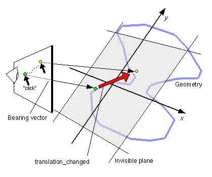
is sent. Pointer motion is mapped into relative translation in a plane
parallel to the sensor's local Z=0 plane and coincident with the initial
point of intersection. For each subsequent movement of the bearing,
a translation_changed event is output which corresponds to the
sum of the relative translation from the original intersection point
to the intersection point of the new bearing in the plane plus the offset
value. The sign of the translation is defined by the Z=0 plane of the
sensor's coordinate system. trackPoint_changed events reflect
the unclamped drag position on the surface of this plane. When the pointing
device is deactivated and autoOffset is TRUE, offset is
set to the last translation_changed value and an offset_changed
event is generated. More details are provided in "2.6.7.4
Drag sensors."
When the sensor generates an isActive TRUE event, it grabs
all further motion events from the pointing device until it is deactivated
and generates an isActive FALSE event. Other pointing-device
sensors cannot generate events during this time. Motion of the
pointing device while isActive is TRUE is referred to as a "drag."
If a 2D pointing device is in use, isActive events typically
reflect the state of the primary button associated with the device (i.e., isActive
is TRUE when the primary button is pressed, and is FALSE when it is
released). If a 3D pointing device (e.g., wand) is in use, isActive
events typically reflect whether the pointer is within or in contact
with the sensor's geometry.
minPosition and maxPosition may be set to clamp translation_changed
events to a range of values as measured from the origin of the Z=0 plane.
If the X or Y component of minPosition is greater than the corresponding
component of maxPosition, translation_changed events are
not clamped in that dimension. If the X or Y component of minPosition
is equal to the corresponding component of maxPosition, that
component is constrained to the given value. This technique provides
a way to implement a line sensor that maps dragging motion into a translation
in one dimension.
| TIP:
Setting a minPosition and maxPosition for one dimension,
and setting minPosition = maxPosition for the other
dimension, is the foundation for a slider user interface widget.
VRML 2.0 does not define standard user interface components like
sliders, buttons, and so forth. Instead, building blocks like PlaneSensor,
TouchSensor, geometry, and Script are provided to allow many different
types of user interface components to be built. The prototyping
mechanism is provided so that these components can be easily packaged
and reused once they have been built. Interaction on a 2D desktop
is a well understood problem, suitable for standardization, while
user interaction in a 3D world is still in the research and experimentation
stages. |
While the pointing device is activated and moved, trackPoint_changed
and translation_changed events are sent. trackPoint_changed
events represent the unclamped intersection points on the surface of
the local Z=0 plane. If the pointing device is dragged off of the Z=0
plane while activated (e.g., above horizon line), browsers may
interpret this in a variety ways (e.g. clamp all values to the horizon).
Each movement of the pointing device, while isActive is TRUE,
generates trackPoint_changed and translation_changed events.
Further information about this behaviour may be found in "2.6.7.3 Pointing-device sensors", "2.6.7.4
Drag sensors", and "2.6.7.5 Activating
and manipulating sensors."

Figure 3-42: PlaneSensor Node
| TIP:
It is usually a bad idea to route a drag sensor to its own parent.
Typically, the drag sensor will route to Transform, which does not
affect the sensor. See the following examples. |
| TECHNICAL
NOTE: A PlaneSensor that is not oriented almost perpendicular
to the viewer can be very difficult to control. Small movements
of the pointer can result in very large translations, because
the plane and the pointing ray are almost parallel. The specification
is a little bit vague about what to do about such cases, guaranteeing
only that the trackPoint will accurately represent the last intersection
of the pointing ray with the plane. Implementations are left free
to experiment with schemes to control the translation_changed
events that are generated to make it easier for users to control.
|
| TIP:
Combining PlaneSensor with other features produces some neat
features. Putting a PlaneSensor underneath a Billboard node
results in a PlaneSensor that always turns to face the user,
which can make a user interface component built from a PlaneSensor
much easier to control. Combining a PlaneSensor, ProximitySensor,
and a Transform node can result in a PlaneSensor that is always
in front of the user. Again, this can be very useful, since
one big problem with user interface controls in a 3D world is
that it is easy for the user to lose them. Combining these two
techniques can give you a PlaneSensor that is always in front
of the user and is always oriented with the computer screen.
In that case, the PlaneSensor will produce values that are almost
raw mouse x, y positions (almost because the positions will
be off by constant scale and offset factors). |
|
EXAMPLE
(click to run) :
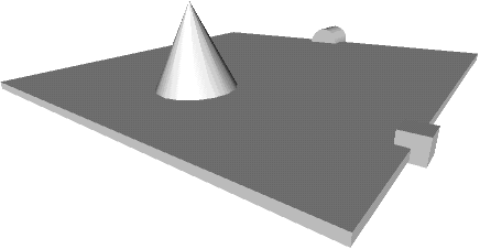
The following example illustrates a simple case of the PlaneSensor
node (see Figure 3-43). It uses three PlaneSensors
to translate a Cone in a restricted rectangular area. Notice
how the Transforms are used to rotate the PlaneSensors into
the XY plane (since the default orientation for a PlaneSensor
is the XY plane). The second two PlaneSensors illustrate
how to create 1D sliders by taking advantage of the minPosition
and maxPosition fields:
#VRML V2.0 utf8
Group { children [
Transform { # Create the object to be xlated
translation 0 1 0
rotation 1 0 0 1.57 # Rotate sensor into XZ plane
children [
DEF PS1 PlaneSensor {
minPosition -5 -5
maxPosition 5 5
}
DEF T1 Transform {
rotation 1 0 0 -1.57 # unrotate cone upright
children Shape {
appearance DEF A1 Appearance {
material Material { diffuseColor 1 1 1 }
}
geometry Cone { bottomRadius 1 height 2 }
}
}
]
}
Transform { # Create Z slider
translation 5 0 0
rotation 1 0 0 1.57
children [
DEF PS2 PlaneSensor {
minPosition 0 -5 # Restrict xlation to Z axis
maxPosition 0 5
}
DEF T2 Transform { # Z Slider's thumb geometry
children Shape {
geometry Box { size .5 .5 .5 }
appearance USE A1
}
}
]
}
Transform { # Create X slider
translation 0 0 -5
rotation 1 0 0 1.57
children [
DEF PS3 PlaneSensor {
minPosition -5 0 # Restrict xlation to X axis
maxPosition 5 0
}
DEF T3 Transform { # X Slider's thumb geometry
children Shape {
geometry Cylinder { radius 0.5 height 1 }
appearance USE A1
}
}
]
}
Transform { # table
translation 0 -0.1 0
children Shape {
geometry Box { size 10 0.2 10 }
appearance USE A1
}
}
Background { skyColor 1 1 1 }
NavigationInfo { type "EXAMINE" }
]}
ROUTE PS1.translation_changed TO T1.set_translation
ROUTE PS2.translation_changed TO T2.set_translation
ROUTE PS2.translation_changed TO T1.set_translation
ROUTE PS3.translation_changed TO T3.set_translation
ROUTE PS3.translation_changed TO T1.set_translation
ROUTE PS2.offset_changed TO PS1.set_offset
ROUTE PS3.offset_changed TO PS1.set_offset
|

Figure 3-43: PlaneSensor Example
|

