|
Chapter 3:
Node Reference
Intro
Anchor
Appearance
AudioClip
Background
Billboard
Box
Collision
Color
ColorInterpolator
Cone
Coordinate
CoordinateInterpolator
Cylinder
CylinderSensor
DirectionalLight
ElevationGrid
Extrusion
Fog
FontStyle
Group
ImageTexture
IndexedFaceSet
IndexedLineSet
Inline
LOD
Material
MovieTexture
NavigationInfo
Normal
NormalInterpolator
OrientationInterpolator
PixelTexture
PlaneSensor
PointLight
PointSet
PositionInterpolator
ProximitySensor
ScalarInterpolator
Script
Shape
Sound
Sphere
SphereSensor
SpotLight
Switch
Text
TextureCoordinate
TextureTransform
TimeSensor
TouchSensor
Transform
Viewpoint
VisibilitySensor
WorldInfo
|
TextureTransform {
exposedField SFVec2f center 0 0 # (- ,)
exposedField SFFloat rotation 0 # (-,)
exposedField SFVec2f scale 1 1 # (-,)
exposedField SFVec2f translation 0 0 # (-,)
} ,)
exposedField SFFloat rotation 0 # (-,)
exposedField SFVec2f scale 1 1 # (-,)
exposedField SFVec2f translation 0 0 # (-,)
}
The TextureTransform node defines a 2D transformation that is applied
to texture coordinates (see 3.48 TextureCoordinate).
This node affects the way textures coordinates are applied to the geometric
surface. The transformation consists of (in order):
- a translation,
- a rotation about the centre point,
- a non-uniform scale about the centre point.
These parameters support changes to the size, orientation, and position
of textures on shapes. Note that these operations appear reversed
when viewed on the surface of geometry. For example, a scale
value of (2 2) will scale the texture coordinates and have the net effect
of shrinking the texture size by a factor of 2 (texture coordinates
are twice as large and thus cause the texture to repeat). A translation
of (0.5 0.0) translates the texture coordinates +.5 units along
the S-axis and has the net effect of translating the texture -0.5 along
the S-axis on the geometry's surface. A rotation of  /2
of the texture coordinates results in a -/2 rotation of the texture on the
geometry. /2
of the texture coordinates results in a -/2 rotation of the texture on the
geometry.
The center field specifies a translation offset in texture
coordinate space about which the rotation and scale fields
are applied. The scale field specifies a scaling factor in S
and T of the texture coordinates about the center point. scale
values shall be in the range (-, ). The rotation field specifies
a rotation in radians of the texture coordinates about the center
point after the scale has been applied. A positive rotation value makes
the texture coordinates rotate counterclockwise about the centre, thereby
rotating the appearance of the texture itself clockwise. The translation
field specifies a translation of the texture coordinates.
In matrix transformation notation, where Tc is the untransformed
texture coordinate, Tc' is the transformed texture coordinate,
C (center), T (translation), R (rotation),
and S (scale) are the intermediate transformation matrices,
Tc' = -C × S × R × C × T × Tc
Note that this transformation order is the reverse of the Transform
node transformation order since the texture coordinates, not the texture,
are being transformed (i.e., the texture coordinate system).
| TIP:
TextureTransform should have been named TextureCoordinateTransform,
since it does not transform texture maps, but transforms texture
coordinates. This is a subtle yet critical distinction that must
be understood before using this node. In short, all operations have
the inverse effect on the resulting texture. Texture coordinates
are very much like vertex coordinates. They are specified in a local
coordinate system, can be transformed (using a TextureTransform
node), and the transformed coordinates specify a particular location
in some space. One difference is that vertex coordinates are transformed
into "world space"--the xyz space in which the virtual world is
constructed. Texture coordinates are transformed into "texture image
space"--the 0 to 1st space of a texture image. However, it is difficult
to think in terms of the texture coordinates being transformed,
because the texture image is transformed (warped) to be displayed
on the screen. To think in terms of the texture image being transformed
first by the TextureTransform and then by the given TextureCoordinates,
everything must be reversed, resulting in the nonintuitive behavior
that specifying a scale of two for a TextureTransform results in
a half-size texture image. |
| TECHNICAL
NOTE: Animating a TextureTransform can produce interesting effects
such as flowing water or billowing curtains. However, animating
TextureTransforms is not a common enough operation to justify the
inclusion of special 2D interpolator nodes, so you must write a
Script node to interpolate the SFVec2f values of a TextureTransform's
translation, scale, or center fields. |
EXAMPLE
(click to run):
The following example illustrates the TextureTransform node (see
Figure 3-60). All five rectangles share an identical geometry,
material, and texture map while varying the values of the TextureTransform.
The first rectangle illustrates the rectangle with no TextureTransform
applied. Notice how the TextureCoordinate node repeats the texture.
The second rectangle sets the scale field of the TextureTransform.
Notice that scale values > 1.0 reduce the resulting texture on
the rectangle because TextureTransform transforms the texture coordinates,
not the texture map (and conversely, scale values < 1.0 will
enlarge the resulting texture). The third rectangle sets the translation
field of TextureTransform and has the net effect of translating
the texture to the left and down (rather than to the right and up,
as might be expected). The last rectangle shows the combined effect
of the scale, rotation, and translation fields:
#VRML V2.0 utf8
Group { children [
  Transform {
    translation -5 0 0
    children Shape {
      appearance Appearance {
        texture DEF IT ImageTexture { url "marble2.gif" }
        material DEF M Material { diffuseColor 1 1 1 }
      }
      geometry DEF IFS IndexedFaceSet {
        coord Coordinate {
          point [ -1 -1 0, 1 -1 0, 1 1 0, -1 1 0 ]
        }
        coordIndex [ 0 1 2 3 ]
        texCoord TextureCoordinate {
          point [ 0 0, 3 0, 3 3, 0 3 ]
        }
      }
    }
  }
  Transform {
    translation -2.5 0 0
    children Shape {
      geometry USE IFS
      appearance Appearance {
        material USE M
        texture USE IT
        textureTransform TextureTransform {
          scale 2 2
        }
  }}}
  Transform {
    translation 0 0 0
    children Shape {
      geometry USE IFS
      appearance Appearance {
        material USE M
        texture USE IT
        textureTransform TextureTransform {
          translation .5 .5
        }
  }}}
  Transform {
    translation 2.5 0 0
    children Shape {
      geometry USE IFS
      appearance Appearance {
        material USE M
        texture USE IT
        textureTransform TextureTransform {
          rotation .785
        }
  }}}
  Transform {
    translation 5 0 0
    children Shape {
      geometry USE IFS
      appearance Appearance {
        material USE M
        texture USE IT
        textureTransform TextureTransform {
          translation .5 .5
          rotation .7
          scale 0.25 0.25
        }
  }}}
  Background { skyColor 1 1 1 }
]}
|
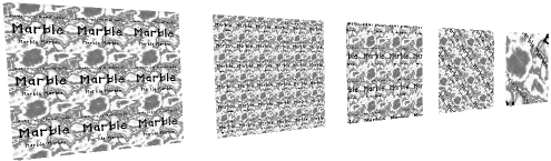
Figure 3-60: TextureTransform Node Example
|